'+ data.data.username +' '; dom + ='
1. When the long-wave transmission line is under high-frequency conditions, when electromagnetic waves propagate along the transmission line, due to the short wavelength of electromagnetic waves, different phenomena will occur on the transmission line than when transmitting audio signals. It must be used. .
When the wavelength of the electromagnetic wave propagating along the transmission line can be compared with the geometric length of the transmission line, the transmission line at this time is usually called a long line.
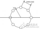
1. There is uneven distribution of current and voltage on the long line: take a transmission line with a length of 10 meters, when high-frequency current is passed on the line (long line case), such as F = 150MHZ. People (wavelength) = 2 meters due to the short wavelength , The current in the transmission line has several periods of change, as shown in Figure A. Therefore, the current magnitude and direction at each point on the line are different at the same time; and at low frequencies (that is, in the short-term case) For example, the alternating current of F = 50HZ has an operating wavelength of 6,000 kilometers and a difference of 3,000,000.The same is the case that the current on the 10-meter long transmission line rarely changes and can be considered unchanged.
2. The long line is a distributed parameter system: for the long line, with the length of the transmission line or the wavelength of the electromagnetic wave propagating along the line, there are distributed capacitance and distributed inductance parameters on the transmission line itself. And these distribution parameters have a great influence In the case of long wires, due to different wire lengths or different operating wavelengths, the transmission line itself will exhibit different impedances (capacitive reactance, inductive reactance, or pure resistance). On the short line, only the capacitor has the electric field, coil The magnetic field is generated only in the middle, and has nothing to do with the line length. 
2. Transmission line with open terminal When the transmission line receives a signal, the electrical signal will propagate to the terminal at the speed of light according to the cosine distribution. Because the terminal is open, the signal cannot continue to propagate forward, and it will form a total reflection in the direction of the beginning, which is equivalent to A signal source is connected to the terminal of the transmission line so that the electrical signal propagates from the terminal to the beginning at the speed of light. Generally speaking, the electric wave propagating from the beginning to the terminal is called the incident wave; the electric wave reflected by the terminal is called the reflected wave. The reflected waves are all traveling waves. The so-called traveling waves here are the electric waves with the voltage and current in phase.
The discussion of the transmission line also introduces the concept of a standing wave. The so-called standing wave is that the phase of the voltage and current is different and the phase difference is one-quarter wavelength, and the amplitude of the voltage and current is unevenly distributed. In the open-ended transmission line, there are both reflected waves and incident waves. Waves, reflected wave currents and incident wave currents have opposite phases, so there are standing waves on the transmission line, usually there are both traveling waves and standing waves on the transmission line, and traveling waves and standing waves are caused by incident waves and reflected waves. Because of the total reflection, the standing wave component of the open-ended transmission line is very large, so there is no energy transmission (the energy transmission is only on the line in the traveling wave state) .Assuming that the transmission line is lossless, then only Store energy in a certain period and release energy in another period. So for the signal source, it is a purely reactive load. The transmission line with an open circuit at the terminal has the following characteristics. When the transmission line is less than a quarter wavelength, it is The reactance is capacitive; when it is equal to a quarter wavelength, the reactance is zero; when it is greater than a quarter wavelength, the reactance is inductive; when it is equal to a half wavelength, it is purely resistive.
3. Transmission line with short-circuited terminal The transmission line with short-circuited terminal is opposite to the transmission line with open terminal. Its standing wave characteristic is that the incident current is in phase with the reflected wave current, and the incident wave voltage is in phase with the reflected wave voltage. Its impedance characteristic is less than a quarter The transmission line is inductive at one wavelength; purely resistive when it is equal to one-quarter wavelength; capacitive when it is greater than one-quarter wavelength; the reactance is zero when it is equal to one-half wavelength.
In general, the terminals of the transmission line are connected to a load, and the load usually has both a resistance component and a reactance component.Therefore, part of the energy output by the signal source is absorbed by the load and the other part will be reflected back, so the uplink and the standing wave of the transmission line are simultaneously Coexistence, in order to further describe the distribution relationship between the upward wave of the line and the standing wave, we introduce several specific indicators:
1. Reflection coefficient: P = reflected wave amplitude / incident wave amplitude = transmission line characteristic impedance-load impedance / transmission line characteristic impedance + load impedance
2. Traveling wave coefficient: K = minimum voltage / maximum voltage = reflected wave amplitude-incident wave amplitude / reflected wave amplitude + incident wave amplitude. Because there are both incident and reflected waves in the transmission line, at any point on the transmission line The voltage is the sum of the amplitudes of the two waves.
3. Standing wave ratio: S = voltage maximum value / voltage minimum value. In summary, when the transmission line terminal is loaded, the transmission line input impedance has the following properties:
1. The equivalent impedance at the odd multiple of the quarter wavelength from the terminal on the transmission line is equal to the square of the characteristic impedance divided by the terminal load.
2. The equivalent impedance at a half-wavelength integer from the terminal on the transmission line is equal to the load impedance.


Follow WeChat

Download Audiophile APP

Follow the audiophile class
related suggestion
Now, the next generation of communication technology-5G has entered the end of the standard formulation stage, and major operators are also actively deploying 5G equipment. Needless to say ...

Mobile communication antenna application frequency bands are currently mainly concentrated below 6GHz. Mobile communication antennas are moving towards multi-frequency, multi-beam, active integration, smart ...

With the rapid development of trunking communications in China, the 600-pair frequency resources in the 800MHz band are becoming increasingly tense. In response to this situation, China ...

Multi-antenna technology refers to wireless communication technology that uses multiple antennas at the sending end or the receiving end, and is one of the hottest research technologies that have developed rapidly in the near future. use...

According to the work deployment of the Ministry of Industry and Information Technology, China's IMT-2020 (5G) promotion group, and the 5G commercial plan of the three major operators, China will ...
With the development of modern radio technology, wireless communication systems have become more and more common in point-to-point information transmission. Compared with cable and optical fiber communication, microwave communication ...

The new mobile phone antenna puts forward new requirements for antenna technology, and it also prompts the emergence of new technologies. Today we will introduce the most common LDS technology for everyone ...

The application of radio frequency identification (RFID) technology in logistics material distribution, manufacturing, and postal service has become quite common. ## Results and ...

LDS antenna technology is Laser-Direct-structuring technology, using computer ...

National Instruments (National Instruments, referred to as NI) from November 5, 2012 to ...

Starting with the "2011 International Modern Hospital Exhibition" (July 13-15, 2011), medical exhibitions have been held successively in Japan in recent weeks. ...

Molex, the world's leading supplier of complete interconnect products, releases detailed information on its innovative antenna technology. MobliquA ™ antenna technology ...
This article mainly introduces the definition characteristics, transmission mode, performance analysis, channel control coverage, application scenarios and international commercial situation of multi-antenna technology.

Antenna Technology I. Long-line transmission line When the electromagnetic wave propagates along the transmission line at a high frequency, the ...

Antenna Technology 1. Transmission line with open terminal When the transmission line receives a signal, the electrical signal will be light ...

1 antenna
![[Photo] Basic knowledge of antenna](http://i.bosscdn.com/blog/20/06/41/5211351344.jpg)

Privacy statement: Your privacy is very important to Us. Our company promises not to disclose your personal information to any external company with out your explicit permission.

Fill in more information so that we can get in touch with you faster
Privacy statement: Your privacy is very important to Us. Our company promises not to disclose your personal information to any external company with out your explicit permission.