![]()
Car Audio Crystal 3.2*2.5mm 3225 24M (24.000MHZ) 20PF 10PPM 20PPM 30PPM
![]()
Murata muRata winding inductance original authentic assured purchase

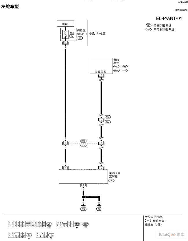
Scorpio A33-EL audio antenna circuit diagram
Power supply:
The Scorpio A33-EL audio antenna circuit first requires a stable power supply, which usually comes from the vehicle's battery system or a dedicated power module.
The power supply may include components such as power filters and voltage regulators to ensure a stable power supply for the audio antenna.
Control unit:
The control unit is the core of the audio antenna circuit, responsible for receiving signals from the vehicle's audio system or other control sources, and controlling the antenna's movements based on these signals.
The control unit may be an independent circuit board that integrates components such as a microcontroller and logic circuits.
Antenna driver:
The antenna driver is responsible for receiving signals from the control unit and converting them into current or voltage that can drive the antenna to move.
The driver may include components such as motor drivers and relays to drive the movement of the audio antenna, such as telescoping, rotating, etc.
Audio antenna:
The audio antenna is the output part of the system, responsible for receiving and sending audio signals.
Depending on the specific configuration of the Scorpio A33-EL and the requirements of the audio system, the audio antenna may have a specific shape, size, and function.
Connectors and cables:
Connectors and cables are used to connect the power supply, control unit, antenna driver, and the audio antenna itself.
These connectors and cables need to have good electrical performance and durability to ensure the stability and reliability of the audio antenna circuit.
Protection circuit:
In order to protect the audio antenna circuit from abnormal conditions such as overcurrent and overheating, it may be necessary to design corresponding protection circuits.
The protection circuit may include components such as fuses, thermistors, and overcurrent protectors.
Fault diagnosis and indication:
In order to facilitate users or maintenance personnel to detect and diagnose possible faults in the audio antenna circuit, it may be necessary to design corresponding fault diagnosis and indication functions.
This may include fault indicators such as indicator lights and buzzers, as well as related fault diagnosis interfaces or software.
Wifi Antenna, Router Antenna, Patch Antenna


