Privacy statement: Your privacy is very important to Us. Our company promises not to disclose your personal information to any external company with out your explicit permission.
introduction:
The SoPC-based automotive safety monitoring system uses Altera's latest SoPC (Programmable System-on-Chip) solution, the Nios processor soft core, to monitor the parking and operating status of the car with GPS and GSM systems.
The SoPC-based vehicle safety monitoring system can be widely used in the anti-theft, routine maintenance and traffic accident handling of automobiles, providing an effective test method for vehicle faults.
1 system hardware components
The design uses Altera's SoPC development tools. The development of the system includes two major parts of hardware and software. Using SoPC Builder to generate Nios embedded processors, Nios embedded processor development tools allow users to configure one or more Nios CPUs, add peripherals from the standard library, integrate custom systems, and compile the system with Quartus II design software. The steps of software development are: using the software files generated by SoPC Builder, writing assembly language or C/C++ source program with text editor, programming, building and debugging with GNUPro software development tools. GNUPro builds source programs (including assembly/compilation and linking) into executable programs, and debugs and runs executable programs through download cables. Quartus II design software provides a comprehensive and efficient design environment that integrates design, synthesis, layout and validation, as well as third-party EDA tool interfaces in a seamless environment. You can create your own Nios CPU system with SoPCbuilder integrated in the Quartus II 3.0. Nios is a 16/32-bit embedded processor soft core developed by Altera Corporation.
The school research fund project "SOPC-based vehicle safety monitoring system" is funded. Altera Corporation has introduced a new generation of FPGAs. The design uses the low-cost Cyclone series EP1C12, which has 12 060 logic cells, 52 M4K RAM blocks, 239 616 RAM bits and 2 phase-locked loops. I/O pin 249.
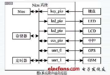
The block diagram of the system hardware consists of two parts, the Nios system and the external device, as shown in Figure 1. 
Nios system includes CPU (Nios), memory (memory), timer (timer), bus and parallel/serial interface (key_pio, led_pio, lcd_pio, ccs_pio, uart_0, and uart_1), etc., and the serial interface is implemented separately with the keyboard. , LED and LCD displays, automotive central control systems, and connections to external devices such as GPS and GSM systems. The Nios system design and design results are shown in Figure 2 and Figure 3, respectively. 

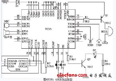
The Nios system is relatively simple to connect to external devices such as keyboards, LEDs and LCD monitors, automotive central control systems, and GPS systems. The connection to the GSM system is complex, as shown in Figure 4. 
The whole system works as follows: information from the car's central control system and GPS system can be displayed on the LED and LCD display, or wirelessly via the GSM system. The user can control the system through the keyboard, or remotely control the car's central control system through the GSM system.
This article refers to the address: http://
June 28, 2024
Mail an Lieferanten
June 28, 2024

Privacy statement: Your privacy is very important to Us. Our company promises not to disclose your personal information to any external company with out your explicit permission.

Fill in more information so that we can get in touch with you faster
Privacy statement: Your privacy is very important to Us. Our company promises not to disclose your personal information to any external company with out your explicit permission.